Ethernet MeterBus Converter

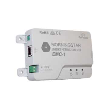


The Ethernet MeterBus Converter™ (model: EMC-1) provides the data and communications connection for Morningstar devices, between themselves, with surrounding systems, and with the outside environment through the internet. It’s simple to connect to Morningstar products equipped with an RJ-11 Meterbus port to enable remote monitoring, custom programming, and access to future cloud-based data services.
Protocols and technologies supported by the EMC-1 include:
- HTTP for LiveView: a simple and straightforward web dashboard for checking system status easily from any device browser
- SNMP (Simple Network Management Protocol): provides more detailed monitoring of all system data with existing IT management architecture
- MODBUS Industrial Control: provides high-speed monitoring and control for industrial equipment Compatible Morningstar products include:
- MPPT controllers: TriStar MPPT, ProStar MPPT, and SunSaver MPPT
- PWM controllers: TriStar, ProStar (Gen3) and SunSaver Duo
- Inverters: SureSine
The EMC-1 converts this connection into a fully enabled Ethernet port allowing data transfer to the internet. Once connected, the MeterBus port enables transmission of serial data to the EMC-1 for remote monitoring, configuration, and control, using any type of IP-based network connection. This way, many new, powerful integration options for Morningstar products can be activated and used in remote power systems.
Specifications and Certifications by Model
| Model | EMC-1 |
|---|---|
| DC Input Supply Voltage Range | 8-80 Vdc |
| Maximum Self Consumption | 2 Watts |
| Operating Temperature Range | -40 C to +60C |
| Warranty | 5 Years |
| CE and RoHS | Yes |
| FCC Class B Part 15 Compliant | Yes |
| Manufactured in a Certified ISO 9001 Facility | Yes |
- Adds SNMP to deliver real-time system data
- Enables Live View to display system status and log data directly from the EMC, in an easy-to-view webpage
- Adds IP-based MODBUS connectivity for remote
industrial communication and control - Connects to any MeterBus-enabled controller to provide enhanced data and network features
- Powered via MeterBus port on controller or DC Input for 12, 24 or 48V systems
Ethernet MeterBus Converter (EMC-1) | 3-Minute Video
This 3 minute video provides an overview of Morningstar’s new Ethernet MeterBus Converter (EMC-1). This device enables IP based network and internet connectivity to any Morningstar solar charge controller or inverter that features an existing MeterBus port (RJ-11) including: PWM controllers: TriStar and SunSaver Duo; MPPT controllers: TriStar MPPT, ProStar MPPT, & SunSaver MPPT; Inverters: SureSine. And future products that feature an existing MeterBus port (RJ-11).
Ethernet MeterBus Converter Webinar | Recorded Webinar
View this recorded webinar to learn about the new Ethernet MeterBus Converter which enables the addition of IP based network and internet connectivity to any Morningstar product that features an existing MeterBus port (RJ-11).
Related Products
System Diagram
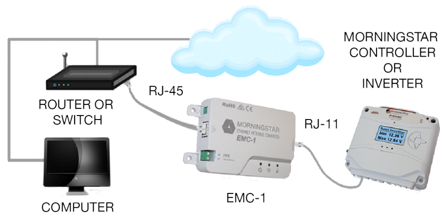
The diagram above shows how connections are made with the RJ-11 cord between the Morningstar product on the right and the EMC-1 in the middle. The EMC-1 is connected to an Ethernet gateway which is typically a router or switch that you see on the left.
Select Morningstar products that previously could not connect to an IP network or internet can connect to the EMC-1 to enable a view of many useful system metrics via web browser such as:
- Battery voltage
- PV current
- Load current
- Faults or errors within the system
This information will appear live in real time, so you will see data changing without having to refresh your browser. Furthermore, you can use our free MSView software with the EMC-1 so you can change your battery charging settings, low voltage disconnect settings, and lighting settings. Every product in MSView has its own setup wizard for adjusting the custom settings. To make it easier to use MSView setup wizards, we’ve created a webpage that lets you download custom settings configuration files.
Off-Grid Diagram with AC Load
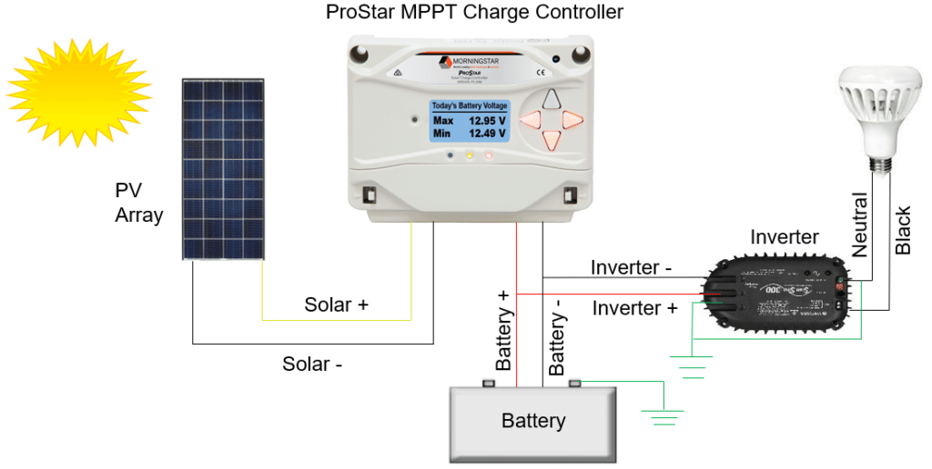
The schematic diagram above, illustrates how the ProStar MPPT regulates power to batteries and an alternating current (AC) load in an off-grid system. This diagram is very similar to the DC load diagram above it except an inverter has been added.
- Sunlight contacts the solar modules, which convert solar into DC electrical power that it delivers to a charge controller.
- The charge controller regulates the amperage and voltage that is delivered to the battery system so the batteries maintain their state of charge without getting overcharged.
- Batteries deliver power to the inverter which converts DC to AC power that it delivers to the load. Notice that the inverter is connected to the battery, not the controller’s load terminals, like we did in the DC load example. That’s because the inverter can have a high energy surge upon start up, and this high current surge might be higher than the rated capacity of the charge controller, whereas the batteries will be able to meet the high energy surge requirement.