Solar Charge Controller Best Practices by Battery Chemistry
All Morningstar charge controllers offer complete multi-stage charging profiles for Lead Acid Batteries. However, some Morningstar solar charge controllers can also be used as an effective charging solution for other types of batteries as well. This page and included links provide useful information about Factory Presets or Custom Setup for use with the latest battery chemistries and technologies.
Related Links:
- Custom Settings Info Pages for Battery Manufacturer/Models – Includes downloadable MSView Setup Wizard Files
Battery Types commonly used in solar PV systems include:
- Lead Acid (PbSO4)
- Lithium-Ion (Li-Ion or LIB)
- Lithium Iron Phosphate (“LFP”, LiFePO4)
- Lithium Iron Magnesium Phosphate (LiFeMgPO4)
- Lithium Manganese Oxide (“LMO”, LiMn2O4)
- Lithium Nickel Manganese Cobalt Oxide (“NMC”, LiNixMnyCozO2)
- Nickel–Cadmium (NiCd or NiCad)
- Nickel–Metal Hydride (NiMH or Ni–MH)
- Nickel–Iron (NiFe)
- Nickel–Zinc (NiZn)
- Aqueous Hybrid Ion (Aquion or AHI™)
- Flow or Redox Flow Battery
- Vanadium Redox (VRB)
- Zinc–Bromine (ZnBr2)
- Zinc–Cerium (Zn-Ce)
Lead Acid batteries are still the most commonly used batteries for off-grid and grid-tied solar applications with battery backup. Morningstar controllers include up to seven factory presets which are designed specifically for various types of Lead Acid batteries.
Morningstar controllers support traditional Lead-Acid batteries by default, they can also be used with most other types of batteries. In some cases one of the Morningstar’s factory presets can be used for a certain type of battery, often custom settings may be required or can greatly improve performance.
Whether used to configure or enhance charging algorithms, setup connectivity and daily logged values, or program for specific applications, Morningstar’s simple setup tool, MS View, can accomplish this goal quickly and easily from a PC. The Setup Wizard within MS View offers a “Write to File” function which makes it quick and easy to custom program pre-configured settings that can be tailored for the following solutions.
- Optimized or preferred charging algorithm adjustments
- Charging algorithms for different types of batteries
- Less Common Nominal Battery Voltages (Example: 36V)
Once programmed the custom settings are stored in the controller making the Custom DIP Switch Setting just like the other factory PreSets. Having a customizable preset like this can save both the dealer and customer a lot of time and make selling these batteries much easier. Get started with making custom settings with the Setup Wizard any time by downloading the free MSView Software. For help getting started see the Help Topics Menu. Here is a link to the TriStar MPPT Setup Wizard Help Topics Menu.
Here is a list of Morningstar Products that have an MSView Setup Wizard for Customizable Plug and Play Pre-Configurations and Settings adjustments.
- TriStar MPPT 600V
- TriStar MPPT (150V)
- TriStar (PWM)
- ProStar MPPT
- Prostar (Gen3)
- SunSaver MPPT
- Relay Driver (for Switch Control Circuits)
It is also important to note that certain types of batteries may also include or require additional battery management system (BMS) hardware to manage equalization and protection of the battery cells. Not all BMS hardware will be compatible with Morningstar controllers or may need to be modified if possible to protect the controller or loads from damage. Please see Battery Management Systems (BMS) section below for more information about integrating with BMS.
Many solar controllers on the market are not able to achieve a high degree of voltage accuracy. This could pose problems for any type of battery and some batteries may have more performance issues than others based on accuracy issues. Morningstar manufactures several controllers which have Battery Sense connections available (TriStar, TriStar MPPT (150V & 600V), ProStar) and Remote Temperature sensing (TriStar, TriStar MPPT (150V & 600V), SunSaver MPPT, ProStar) which provide very high charging accuracy.
For all of the Morningstar controllers which can be custom programed with MSView software, the ability to change all the setpoints with a high degree of accuracy is provided. Some of the charging profile adjustments that can be made in the Setup Wizards are as follows.
- Absorption, Float and Equalize Voltage regulation setpoint adjustments
- Absorption and equalize stage regulation periods in minutes can be extended or shortened
- Float and Equalize stages can be eliminated
- Other settings such as Float timeouts, Float cancel and High Voltage Disconnect can be edited
- Temperature Compensation can be adjusted or eliminated completely. (note: not connecting the Remote Temperature Sensor (RTS) to the TriStar family of controllers eliminates Temperature Compensation for those products)
- For controllers with an RTS it is possible to add a relay controlled switch to shut down charging or with a small resistor instantly shift the voltage setpoint. See RTS Relay External Control section
Once programmed, the settings are permanently stored in the controller and can be used like one of the presets. In addition, the custom setpoint configuration can be saved as a file so many controllers can be quickly programed with the custom settings specific for a certain battery type. This allows OEM’s, Dealers and Installers to offer a customized PreSet for any type of battery they want.
What if an installer or customer decides that they don’t like the settings or they find out that it isn’t working as well as it could? With MSView they can connect to the controller, read the setpoints, edit the settings and reprogram the controller in just a few minutes. They might also want to save the new settings so they can use them again with other controllers.
MSView is a free software program. Once installed one of the Setup Wizards in the Tools menu can be used to create a new custom setup.
All information regarding battery chemistries, technologies, charging settings or battery behavior is provided to help in the system designing process and may or may not be valid for a specific battery model. Please refer to the specifications and charging information provided by the battery manufacturer to verify any information that is presented. It may be necessary to contact battery manufacturers or dealers to verify or receive further information regarding specific charging requirements.
Please let us know if you are interested in having Morningstar include information for other types of batteries or manufacturers and models. Using the Technical Support Request from the Contact page, include “Non-Lead Acid Battery” in the Summary line.
Helpful Morningstar Links:
Commonly used Communications Adaptors:
- For SunSaver MPPT only:
- For TriStar and TriStar MPPT (30A and 45A):
- Tripp Lite USB / Serial DB-9 Adapter: Model # U209-000-R
See Morningstar Communication Document for other communications hardware.
Disclaimer: Morningstar makes no representation, warranty, or assumption of liability regarding the information presented on this website regarding the various charging requirements for any type of battery or model. The material being presented is based on information that has been provided by other parties (such as battery specs and operational parameters) and uses assumptions that may or may not prove to be valid or up to date.
Morningstar offers the same limited warranty for any type of battery as are offered for acid batteries as long as operation is in accordance to the operation ratings and requirements as specified in the operation manuals.
This will include the operation of the controller in accordance with the operation manual and does not cover any incidental or consequential damages of any kind.
Battery Management Systems (BMS)
Certain types of batteries may include or require additional battery management system (BMS) hardware to manage equalization and protection of the battery cells. Not all BMS hardware will be compatible with Morningstar controllers or may need to be modified if possible to protect the controller or loads from damage. The following provides important information about integrating Morningstar controllers with BMS.
BMS is often used, especially for Lithium batteries in particular, for bringing each individual battery cell to the same state of charge (SOC) level and protect the individual cells from over charging and discharging. For this, individual cell charging control is often implemented which no Morningstar controller is capable of. The Battery Management System (BMS) is often included in the battery itself and controls the individual cell voltages. Interaction between Morningstar Controllers and BMS’s can be simple or problematic depending on how the BMS works. Not all BMS’s operate the same so it is not practical to offer a standard lithium battery preset.
BMS’s Which Can Disconnect from the Solar Controller
Due to the nature of some batteries, the BMS will often include a cell over-discharge protection system that can completely disconnect the battery from the charging source. Even the small self-consumption power of the controller can put in jeopardy the health of the battery since the SOC of the battery can be extremely low. However, once disconnected the controller shuts off and cannot start charging again in the morning. For marine and mobile applications, there will often be an ignition start feature but it would be better to start charging when solar power is available.
It may be possible to have a separate load control disconnect circuit that will be activated before the batteries main over discharge protective switch. However, the default low voltage disconnect (LVD) of Morningstar controllers of typically 11.5V would have possibly < 2% SOC for some types of batteries. The LVD can be custom programmed with a higher voltage or it may be necessary to have a secondary battery at the site or another voltage source to restart the charging with these types of systems.
In addition, many BMS’s may have an even more problematic disconnect feature when battery voltage gets too high or when there are other faults in the system. With PWM controllers a battery disconnect during operation can cause an overvoltage from the PV array to the loads. If the battery is disconnected before the solar PV array is disconnected with the TriStar MPPT controller it can sometimes cause irreversible damage to the controller. Therefore most faults and over-voltage protection should be designed to disconnect the PV array first or at the same time as the battery if necessary. A relay driven switch at the PV activated by a battery disconnect is not going to protect the loads or the TriStar MPPT from damage since there is a delay from the battery switch and the PV array switch in which time damage can occur.
The following precautions to coordinate the BMS with the TriStar MPPT controller or PWM controllers are optimal.
- The BMS needs to be a little smarter so it only disconnects the relevant circuit rather than simply disconnecting itself completely.
- Over-Voltage:
- The TriStar charging can be shut down with a MODBUS Command.
- Use Remote Temperature Sensor Switching Control Link to shut off charging
- Disconnect the PV, not the loads or the controller battery connection. [Loads reduce voltage]
- LVD: Disconnect the load, not the solar controller or other charging sources.
- Very Low Voltage Disconnect (VLVD): Only disconnect the solar controller after LVD. [If there is any PV power it will not disconnect.]
- Other errors should disconnect everything at once (PV input included) rather than just the battery or disconnect the PV array before the battery disconnect.
Remote Temperature Sensor (RTS) with Relay Switch for External Control
This section describes how to use switching with the Remote Temperature Sensor input for switch-driven voltage regulation adjustments.
Relay Fault Controller Interrupt
Morningstar’s Remote Temperature Sensor (RTS) is used for temperature compensation to adjust battery voltage based on the battery temperature. It is best to place it between batteries to get the most accurate measurement of battery temperature. It might also be necessary to disable temperature compensation by not connecting it or setting it to 0V/°C.
If there is a Remote Temperature Failure it will trigger a Fault and the controller will discontinue charging. See this excerpt from the TriStar MPPT manual.
“Remote Temperature Sensor Failure (R+Y / G+Y)
If a fault in the RTS (such as a short circuit, open circuit, loose terminal) occurs after the RTS has been working, the LEDs will indicate a failure. However, if the controller is restarted with a failed RTS, the controller may not detect that the RTS is connected, and the LEDs will not indicate a problem. A TriStar meter or the PC software can be used to determine if an RTS is detected and working properly.”
Some people have used this Alarm with an external switch to shut down the charging. This can be especially useful for alarms or cell overvoltages with Lithium or other batteries with BMS. When the RTS is reconnected the controller can continue charging normally. However, one of the concerns with this is that if the controller is shut down and restarted with the failed RTS condition, the controller may not detect that the RTS is connected, and the switch will no longer work.
Relay Voltage Shift Info: Instant Target Regulation Voltage (TRV) Adjustment using a Resistor with the Remote Temperature Sensor (RTS)
Instead of using the Fault feature, switching resistors in parallel to the RTS input can simulate different temperatures with the RTS to quickly shift the Target Regulation Voltage (TRV). By using a permanently connected resistor it will avoid the possibility of restarting a controller without detection of an RTS. This method has been tested and found to be quite accurate.
See the RTS Resistance vs. Temperature Table Link for details about the Varistor used with the RTS.
10k ohm ±5% = 25C
Here is a handy online parallel resistor calculator for calculating Rtotal = R1×R2/(R1+R2)
http://www.sengpielaudio.com/calculator-paralresist.htm
Example with two parallel resistors
With a 10k resistor connected to the RTS and then use a small relay to switch ON and OFF a 2.5k resistor in parallel you could switch between the 25C and ~67C which is effectively a ~1.26 V drop in TRV for a 12V battery with the default -.03V/C Temperature Compensation. 42C * (-.03V/C) = -1.26V (with no adjustments to temp. compensation mV/C settings in MSView).
This could also be used to quickly reduce the TRV with the RTS connected but the amount it adjusts will vary depend on the temperature and will reduce the TRV voltage significantly more during colder conditions.
Example with RTS and Resistor in parallel
With the default temperature compensation of -.03V/C for a 12V battery: at -10C, switching in a 2.5k resistor will drop resistance down from 54.5k to 2.39k which corresponds to ~ +61C or a -2.13V drop in TRV. If the battery is 34C switching in a 2.5k resistor will drop resistance down from 6.8k to 1.83k which corresponds to ~ +69C or only a -1.05V drop in TRV.
Maximum Compensation and Temperature Range Settings
It is also possible to make adjustments to the temperature compensation settings in MSView. However, the range is limited to -.32 V/C (regardless of battery voltage). That translates to a -.16 V/C setting for a 24V battery and -.08V/C for a 48V.
Scroll down to the ProStar temp comp graphs to see the clamped min and max. voltage ranges. This means the accuracy of the resistors is not that critical since it will clamp to a fixed voltage outside of the compensation temperature range.
Custom programing with a narrow min/max temp comp. range can provide a very wide window for a particular pair of precise (min. and max.) regulation voltage setpoints.
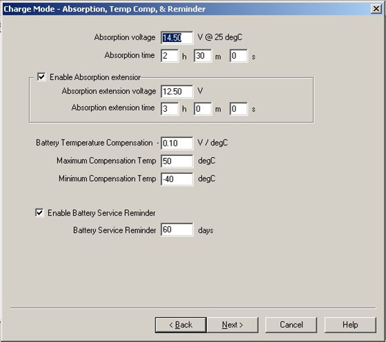
This example shows an adjustment of the battery compensation with .1V/C and a maximum Compensation Temperature of 50C. Therefore switching in a small resistor 1k-4k resistor in parallel with a 10k resistor will provide a 2.5V drop in target regulation voltage. Temperature compensation = (50C-25C)*(-.1V/C) = 25C * .1V/C = – 2.5V
If the minimum voltage was set to 25C in this example both resistors can have a wide range of values.
For further reading, check out Best Battery Chemistry for Off-Grid Solar Applications.