What is a solar charge controller?
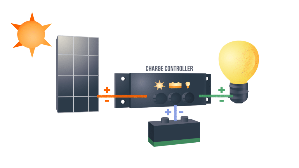
A solar charge controller is an electronic device used in off-grid and hybrid off-grid applications to regulate current and voltage input from PV arrays to batteries and electrical loads (lights, fans, monitors, surveillance cameras, telecom and process control equipment, etc.). The controller safely charges and maintains batteries at a high state of charge without overcharging. A good solar charge controller can extend battery life, whereas a poor quality charge controller can cause battery failure and which causes the entire off-grid system to shut down. Solar charge controllers are also commonly called solar charge regulators.
View our controllers, inverters and accessories pages for information on a specific Morningstar product.
What does a solar charge controller do?
Solar charge controllers are used in off-grid systems to maintain batteries at their highest state of charge without overcharging them to avoid gassing and battery damage. This helps to prolong battery life. Charge controllers also deliver proper current and voltage that meets the rated capacity of electrical loads. Without a charge controller connected to the PV array, the array would deliver too much power which would destroy the batteries and loads.
How does a solar charge controller work?
Solar charge controllers typically deploy either pulse width modulation (PWM) or maximum power point tracking (MPPT) technology to regulate and deliver the right amount of current and voltage from PV arrays to run electrical loads and safely charge batteries during the day. Then during the evening when there is no sunshine, the controller allows the battery bank to run the electrical loads. Solar controllers have electronic protections to protect against nighttime reverse current, short circuiting, high voltage, high temperatures, and battery reverse polarity. Additionally some controllers have low voltage disconnect capabilities and are equipped with LED warning lights to alert about installation errors and faults within the system.
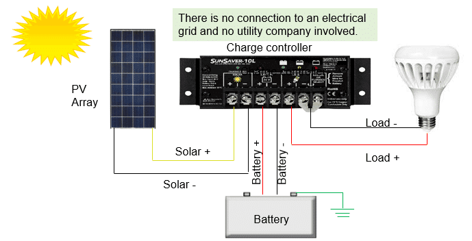
The first solar charge controller schematic below (Figure 1) illustrates how a solar charge controller is connected to power a direct current (DC) load, and the second one (Figure 2) pertains to an alternating current (AC) load.
Figure1: Off-grid Diagram with DC Load
When installing a solar charge controller, it is recommended that you connect and disconnect in the following order:
- Battery to the controller first
- PV array to the controller
- Electrical load to the controller
When disconnecting, you reverse that order. The battery provides power to the controller so always make sure that solar and loads are disconnected before connecting or disconnecting the battery from the controller. Connections between the battery, load, PV array, and the controller should have disconnect switches to enhance safety and facilitate ease of installation and breakdown.
In the wire diagram schematic above with DC load, sunlight contacts the solar modules, which convert solar into DC electrical power that it delivers to a charge controller. The charge controller regulates the amperage and voltage that is delivered to the loads and any excess power is delivered to the battery system so the batteries maintain their state of charge without getting overcharged. During the evening when there is no sunlight, battery power is used to run the load.
You’ll notice that the battery is grounded at the negative battery terminal. This is because all our PWM and MPPT controllers have a common negative ground. Therefore, it is possible to establish a common negative ground for the entire system: the solar array, controller, battery, and load. This meets NEC code requirements for grounding. If you need an equipment ground for any metal parts on a controller enclosure, some of our controllers include an equipment ground terminal lug. Otherwise, for our controllers that don’t have this terminal lug, you can connect an equipment ground directly to the controller enclosure.
The next diagram (Figure 2) depicts the components and connections to power an AC load. This diagram with an AC load looks similar to the previous example with a DC load, except that in this example, we have added an inverter to the system. The purpose of the inverter is to convert the DC power from the battery to AC power that can be used to run an AC load like the TV you see in the schematic.
Figure 2: Off-grid Diagram with AC Load
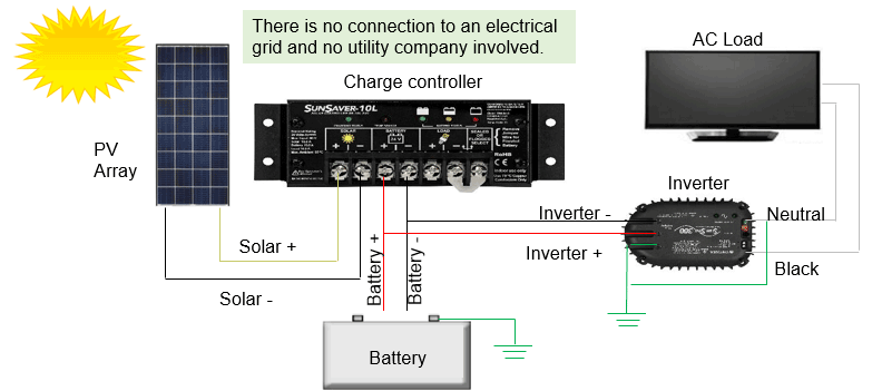
It’s important to note that the inverter is connected and powered from the battery, not the controller’s load terminals like we did in the DC load example. That’s because the inverter can have a high energy surge upon startup, and this high current surge might be higher than the rated capacity of the charge controller, whereas the batteries will be able to meet the high energy surge requirement.
Buy the World’s Leading Solar Charge Controllers
Morningstar charge controllers are the first choice in every challenging solar application—and sometimes the only choice—for mission-critical users. Some are certified for hazardous locations and are standard in the oil & gas industry, for example. Others are proven in demanding telecommunications, mining, security, transportation, and other sectors. Morningstar electronics even power the world’s largest off-grid solar residential project in Peru, supplying electricity to over 200,000 homes. Contact us to find your nearest distributor or talk to a representative about your project.