Describes Basic and Advanced Settings for common and alternative/novel uses for the Relay driver (RD-1).
Click here to download and view the PDF Version.
Morningstar’s Relay Driver (RD-1) is a fully programmable 4-channel logic controller which can be used to control mechanical or solid-state relays in AC and DC power systems. This guide provides an overview of the Relay Driver and includes possible configuration settings and how to apply them to different applications and systems.
Wiring the Relay Driver Channels
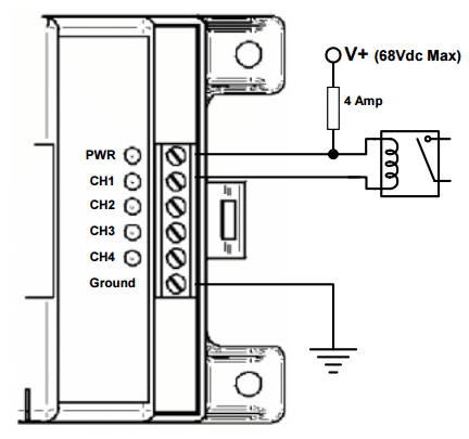 Figure 1: Relay Wiring Diagram
How does it “Drive a Relay”?
Each of the RD-1 Channels is a 750 mA switch that will connect the channel terminal to negative (typically ground) when it is activated. Therefore, it can sink the negative side of a relay coil to ground to activate a relay as shown in the wiring diagram from page 47 of the manual.
Is it possible to power a small load with a RD-1 channel?
Yes. Small DC loads (<750mA) such as LED lights can be powered by the relay channel as indicated on page 49 of the manual.
Can the relay coil or load be powered from another DC power source?
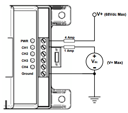 Figure 2: Voltage Measuring Diagram
Yes. As long as the negative/ground is common with the Relay Driver negative/ground and the voltage is less than or equal to the Relay Driver power voltage.
How can a channel measure voltage input?
A channel can be configured to measure external Voltages. The measured voltage must have a negative/ground that is common with the Relay Driver negative/ground and the voltage is less than or equal to the Relay Driver power voltage.
Programming and Logic of the Relay Driver
The Relay Driver uses Boolean logic expressions to determine when to enable the channels.
The manual includes the factory default settings of the 4 channels of the Relay Driver on page 5. There are three (12V nominal) Voltage Threshold settings (2 for LVD and one for simple ON/OFF charging) and the fourth channel is programmed as an Alarm/Fault Monitor. Therefore, it is very common that a custom configuration will need to be programmed into the Relay Driver using the Relay Driver Wizard Tool in Morningstar’s free MSView Software.
MSView Software Download:
https://www.morningstarcorp.com/msview/
The Tripp Lite U209-000-R USB / Serial DB-9 (RS-232) Adapter Cable (found online through various resellers)
Is a USB to RS-232 Serial Adapter which may be used for connecting to PC’s which do not have an RS-232 port.
Simple/Advanced Setup:
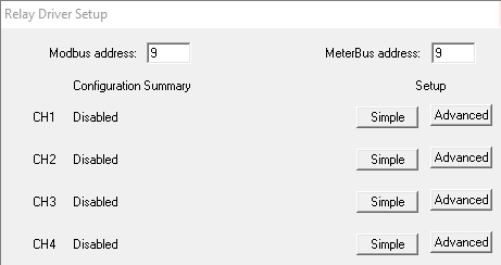 Figure 3: Simple Advanced Setup Selection
The first screen of the Relay Driver Wizard provides the option to program each channel with either Simple or Advanced Settings.
Simple setup allows the user to modify only the most essential settings while using factory default for the more advanced settings.
Note: Simple setup should be used unless there is a specific need to modify an Advanced parameter.
Channel Functions:
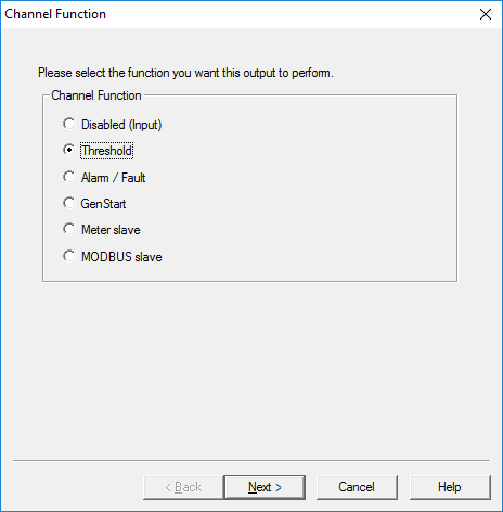 Figure 4: Channel Function Selection
There are several choices of functions.
Disabled (Input)
The Disabled (Input) Function disables the relay driver of a channel. This Function is the “safe” configuration for a channel that is not in use. Disabled channels can be safely used as voltage inputs as well. The channel voltage can be used as a Control Variable for other Functions. It can measure voltages applied from various sensor devices, the state of an ON/OFF switch or to signal the threshold of a voltage being sensed.
Threshold
The Threshold Function switches a channel on or off according to a high threshold setpoint and a low threshold setpoint. When a Control Variable reaches either of these setpoints, the Function switches a channel on or off. Additionally, delays and minimum/maximum timers can further refine its behavior. A variety of control variables may be used including voltage, current, and temperature values.
This makes it very useful for many of the most common functions including LVD, simple ON/OFF charging control, controlling cooling fans based on temperature or even lighting control which is based on PV array voltages.
Alarm / Fault
The Alarm/Fault Function activates a channel in response to a fault or alarm generated by a Morningstar device. Any combination of available faults and/or alarms from a Morningstar Device can be monitored simultaneously. When a Fault or Alarm occurs, the configured channel will turn on.
NOTE: Each channel configured with the Alarm/Fault Function can only monitor the alarm/fault conditions of one device on the Meter Bus network.
Common Applications include setting audible or visual indicators when an alarm or fault occurs in a Morningstar Device or signaling other electronic equipment when an alarm or fault occurs in a Morningstar Device.
GenStart
Configure one or more channels to control a generator. With the flexible parameters of this Function, the user can control 1, 2, or 3-wire schemes. Refer to the generator documentation for required signals, timing, and operating specifications. While some generators can operate with a basic threshold function based on battery voltage thresholds, the GenStart Function provides coordinated ON/OFF switching with with both single and multiple channels which may be required by different generators.
MODBUSTM Slave
Required to be able to control a channel directly via the serial port using the MODBUSTM protocol. By writing a register value (coil command), the output state of a channel can be specified. Relay Driver variables (channel voltages, temperature) can otherwise be read from holding registers via MODBUSTM regardless of the control function assigned.
Control Type (Device):
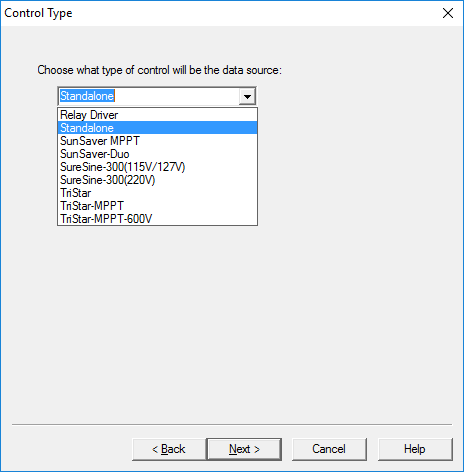 Figure 5: Control Type (Device) Selection
The Control Type specifies the device from which variable data will be polled and used in Threshold, Alarm/Fault and Gen Start Functions.
Use Standalone to poll internal RD-1 variables or select a device from the list of Morningstar devices that you want the Relay Driver to respond to. Standalone is prefered as it does not need to rely on a Meterbus Communications connection.
To select a Morningstar device on a MeterBus network it is necessary to Select Control Address in the window after selecting the device. This is only possible with the advanced setup. The Relay Driver uses the default Meterbus address Of the selected device with the Simple Settings.
Advanced Options
- MeterBus Address (if the device is has been changed from its default MeterBus Address)
- Advanced Threshold and Gen Start Setup
- Delay time to wait for a specific condition to be met. (Also for Gen Start)
- Threshold Minimum High/Low Times set minimum times for Channel states.
- Threshold Maximum High/Low Times set maximum times for Channel states.
- GenStart Maximum Run Time to limit the amount of time a generator can run for at a time.
- GenStart Maximum Off Time to ensure that a generator runs periodically.
- Timing Control (for polling data or standalone condition)
- Sample periods defines how frequently the Relay Driver checks for a condition
- Timeout Options for Communications (not for standalone)
- Time to wait before a communications timeout is declared
- Safe Channel Setting if there is a Communications Timeout
Please read “Relay Driver Setup Wizard” section of Help Topics in MSView for full details regarding these settings.
Types of Relays and Channel ON/OFF Response
An important consideration before programming the Relay Driver is to consider the the type of relays being used and how the Channel ON/OFF logic will affect that particular relay. For voltage and current ratings of relays please contact an electronic parts dealer or distributor or visit their website many of which provide Relay Switch specification selections.
The basic types of Relays are as follows.
- Normally Open (NO) [Channel ON turns on (closes) the relay switch]
- Normally Closed (NC) [Channel ON turns off (opens) the relay switch]
- Double Pole (DP) [Channel ON activates a pair of similar (NO or NC) relay switches]
- Double Throw (DT) [Channel ON turns off (opens) the NC relay switch & turns on (closes) the NO relay switch]
- Time Delay Relays [Triggering the Relay begins a timer for a delay, On time or other internal timer functions.]
- Latching Relays [An ON/OFF pulse triggers the Relay which will maintains its contact position until it receives another ON/OFF Pulse. This can be used to save power.]
Relay Driver Boolean Logic
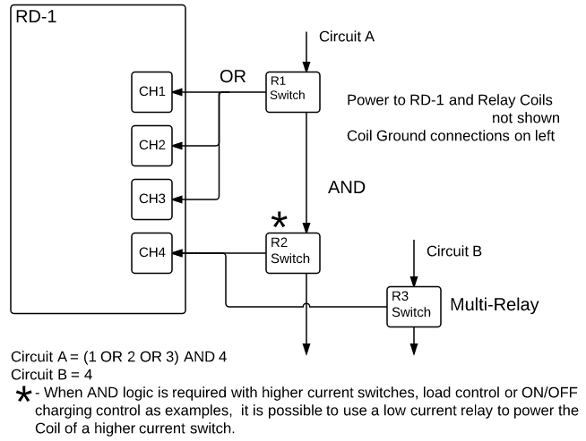 Figure 6: Relay Driver Boolean Logic
It is often useful to employ multiple relays and/or channels together to implement Boolean logic for the system. This diagram shows multiple channels connected to a single relay for OR logic and driving multiple relays with different channels for AND Logic. Since up to 750mA of current can be drawn on each channel, it is also possible to drive multiple relays or loads from a single channel.
Logic Control
- OR logic can be used for triggering one of multiple conditions in the system.
- AND logic can be used for requiring multiple requirements to trigger a switch.
Threshold Function Applications:
General low voltage disconnect
Control Type:
- Via connected controller battery voltage measurement (Select Device and Battery Voltage)
- Via relay driver battery voltage measurement (Select Standalone and Input Voltage)
- Via input channel voltage measurement (Select Standalone or Relay Driver and CH# Voltage)
Simple Setup:
LVD = 11.5V ; LVR = 12.6V
Solution for NC Relay Switch
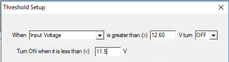 Figure 7: Solution for NC Relay Switch
When Input Voltage is greater than (>) 12.6 V turn OFF
Turn ON when it is less than (<) 11.5V
Solution for a NO Relay Switch
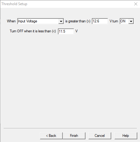 Figure 8: Solution for a NO Relay Switch
When Input Voltage is greater than (>) 12.6 V turn ON
Turn OFF when it is less than (<) 11.5V
Advanced Threshold Setup
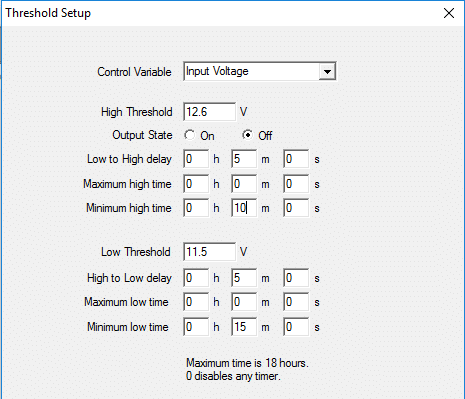 Figure 9: Threshold Setup
The Advanced settings provide delays and Min/Max High/Low Times.
Though the Relay Driver does not have Current Compensation for LVD as there is with Morningstar Controllers the delay (Low to High; High to Low) and minimum Low/High (Channel Output) times will prevent large loads from switching back and forth between LVD and LVR quickly.
The delays prevent momentary voltages from triggering an LVD or LVR prematurely.
The minimum high/low time provides a minimum time for the LVD to stay disconnected or the LVR to remain connected.
Example for NO Relay: LVD = 11.5V ; LVR = 12.6V; 5 minute delays; 10 minute Minimum High/Low times
Maximum Low/High Time would not be considered for LVD settings but might be useful for other applications to limit the time for an ON or OFF condition.
Additional Threshold Function Applications
These Applications use a threshold on a variable that is readily available by the Relay Driver.
- Stand Alone Thresholds
- Voltage of the Power Circuit
- Voltage input on one of the Channel inputs (Input Voltage must be < the RD-1 Power Voltage)
- Variables available with a MeterBus Connection to other Morningstar Products
- Morningstar Controllers or other Relay Drivers connected to the same Meterbus Network
- May include Battery Voltage Battery Current, Array Voltage, Heat Sink Temperature and more
- Enclosure fan on/off control based on temperature input
- Channel to turn on/off fan
- Controlled by
- Heatsink temperature of connected controller
- Input to secondary channel via thermistor / resistor ckt
- Internal or remote (RTS) temperature data from connected controller
- RD-1 ambient temperature
- Generator backup control via battery state
- Controlled by
- Connected controller charging state
- Connected controller battery voltage measurement
- Relay driver battery voltage measurement
- Controlled by
- General low voltage disconnect
- Via connected controller battery voltage measurement
- Via relay driver battery voltage measurement
- Via input channel voltage measurement
- Staged low voltage disconnect
- Via same sources as above
- Disconnect various loads in stages
- More critical loads allowed to stay on at lower battery voltages
- Channel used for each stage disconnect
- Staged reconnect
- Does not have to be in reverse order of disconnect
- New order can be configured for reconnect
Possible Sensor/transducer threshold applications
- Motion sense control
- Motion sensor voltage input to channel
- Secondary channel controls lights, etc based on motion sensor voltage
- Can be combined with low voltage disconnect configured channel
- Motion sensor relay and lvd relay wired in series
- Both must be on for lights on, but only one off to turn off lights
- Water level pump control
- Water (or other liquid) level sensor voltage input to channel
- Secondary channel controls pump based on level sensor voltage
- Can be combined with low voltage disconnect configured channel as above
- Can be staged for multiple pumps or other equipment (pressure release or other valves, etc)
- Backup pump system
- Second voltage input can be used to detect primary pump failure
- If primary pump fails, start secondary pump
- Pressure release valve control
- Similar principle to water level pump control
- Space Heating and Cooling
- on/off control based on temperature input (See fan ON/OFF control)
- Incorporate LVD using Logic (AND)
- Enable Higher Voltage and Charging Current/Power thresholds to utilizing excess power when batteries are mostly full.
- Incorporate delays to wait for a higher SoC after the high voltage threshold
- Maximum High Time can limit the amount of power used at any given time
- Reducing or turning off loads based on reduced charging power (< load power) to prevent discharging of battery.
- Wind Diversion with TS-MPPT
- Basic ON/OFF diversion charging control based on Battery Voltage
- Can be combined with TriStar PWM diversion control with % Duty Cycle response.
Alarm/Fault Setup
Alarm/Fault setup is straightforward and will depend on the device that is connected.
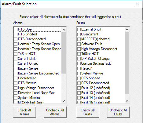 Figure 10: Alarm/Fault Setup
GenStart Setup
Many options are available for GenStart. The Relay Driver has a built-in method for 3 commonly used GenStart methods. Additional logic control can be combined with the RD-1 GenStart settings for more options and feedback.
Simple 2-wire GenStart (Also See GenStart Trigger Settings after the Advanced GenStart Settings section)
Generators will commonly have two single wire methods for Gen Start/Stop control.
The first uses the Run feature shown below for Channel 1 simply to turn on a switch to enable the generator to run and then turning it off to stop running the generator.
The second shown below for Channel 3 uses a latch type of switching system with a momentary ON/OFF switch to start the generator and a momentary ON/Off switch to stop the generator.
The RD-1 GenStart will also be set to enable a load shown below for Channel 2 to turn on after the generator has had time to warm up. The load will also be set to shut off before stopping the generator.
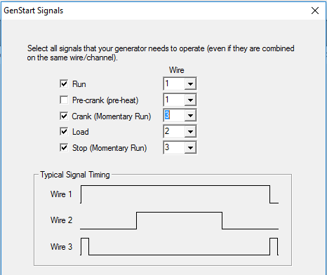 Figure 11: GenStart Signals
Below is an example of the timing setup screen for a Run Timer 2-wire setup.
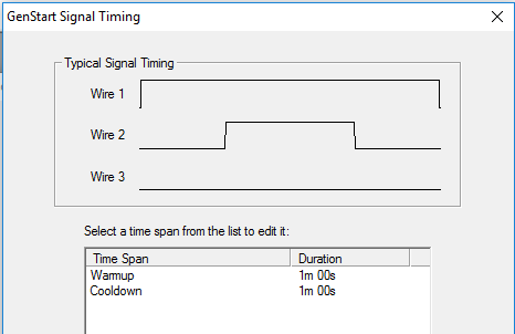 Figure 12: Run Timer 2-wire setup
Below is an example of the timing setup screen for a Momentary ON/OFF Switching 2-wire setup. Please note that Crank is for the Momentary On signal to start the generator.
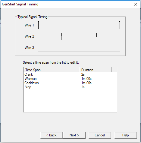 Figure 13: Momentary ON/OFF Switching 2-wire setup
Simple 3-Wire Gen Start (Also See GenStart Trigger Settings after the Advanced GenStart Settings section)
Three Wire systems will also include a switch for cranking the generator.
In addition to cranking the Relay Driver also provides the option for a single pre-crank to preheat the engine some before starting the generator if that is needed. Below is shown the Pre-Crank which will crank the engine for a bit before trying to crank-start and run the generator. The Pre-Crank is optional.
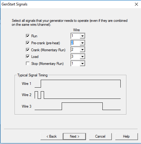 Figure 14: Simple 3-Wire GenStart
Advanced GenStart Settings (Also See GenStart Trigger Settings below)
Maximum On = 3 hours; Limits the maximum generator continuous run time.
Minimum On = 30 minutes; Prevents short run times.
Maximum Off = 21 days; Sets the recommended time to exercise the generator.
Minimum Off = 5 hours; Prevents the Generator from running too frequently.
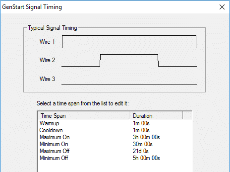 Figure 15: GenStart Trigger Settings
GenStart Trigger Settings
The GenStart Trigger Settings will most typically be based on low voltage to prevent a system LVD for critical loads. Here is an example using a 24V nominal system.
It is also possible to create a GenStart Trigger from other variables such as Load Current for large DC loads to prevent the battery from getting discharged. However, there is just a single GenStart Setting so the only way to add additional triggers is by using Boolean Logic with additional RD-1 channels or other external switches.
Using additional Thresholds or Other External Switches to Enable/Disable GenStart
Below are are some Threshold functions that might be used with AND Logic to
Enable or disable the GenStart Signal switching.
- Charge Controller Current High (Disable)
- Load Control Current High (Enable)
- Temperatures (Too Hot or Too Cold) (Disable)
- Generator Load Off (Disable if Generator did not start)
- Electronic Fuel Gauge (Disable if low)
- ON/OFF Timer Switch for Multiple Cranking/ Disabled by Gen Load circuit On (for Cold locations)
- Manual Switches
- RD-1 MODBUS Control (requires a dedicated Channel)
- RD-1 Input or Channel Voltages