MeterHub

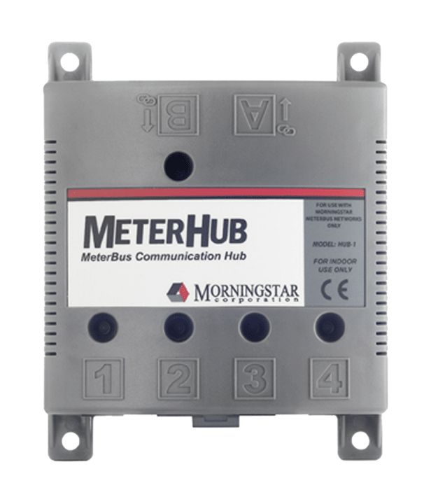
The MeterHub™ allows up to 15 Morningstar products on a single MeterBus network. The product electrically isolates devices that supply power to the network, preventing damage to the network in the event of grounding problems. Five status LED’s indicate the proper network connection to each port.
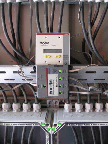
In multi-controller systems the TS-M-2, TS-M-2-600V and TS-RM-2 are networkable using Morningstar’s MeterHub to allow individual controller data and aggregate system data to be displayed together on a single meter. Thus, for example, multiple controllers can share a TriStar Meter or Relay Driver.
The MeterHub is suitable for either wall or DIN rail mounting and it is compatible with:
- TriStar MPPT 600V Controller
- TriStar MPPT Controller
- ProStar MPPT Controller
- SunSaver MPPT Controller
- TriStar Controller
- TriStar Meter 2
- TriStar Remote Meter 2
- Relay Driver
Models: HUB-1,
Specifications & Certifications
| Model | HUB-1 |
|---|---|
| Minimum Isolation (Ports 1-4) | 500V |
| Self Consumption | 8mA |
| Operating Temperature Range | -40 C to +60C |
| Warranty | 5 Years |
| CE and RoHS | Yes |
| ETL Recognized (UL1741) | Yes |
| Manufactured in a Certified ISO 9001 Facility | Yes |
The MeterHub allows up to 15 Morningstar products on a single MeterBus network. The product electrically isolates devices that supply power to the network, preventing damage to the network in the event of grounding problems.